
 Magnetic Sensors
 Pressure Measurement
 Pressure Control
 Liquid Level Measurement
 Temperature Measurement
 Contact
Working Principle of Liquid Level Meter
Liquid level switch, as the name implies, is a
switch used to control the liquid level. It is mainly divided into contact type
and non-contact type. Non-contact type such as capacitive liquid level switch,
contact type such as: float liquid level switch, electrode liquid level switch,
electronic liquid level switch. Capacitive liquid level switch can also be
realized by contact method.
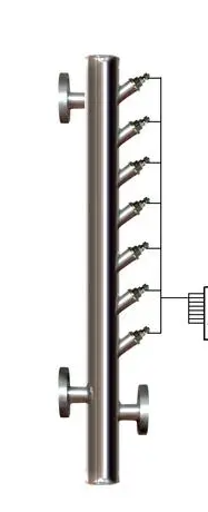
1. Magnetic flap level gauge
Magnetic flap level gauge: also called magnetic float level gauge, magnetic flap level gauge.
Principle: The structure of the float level gauge is designed and produced mainly based on the principles of buoyancy and static magnetic field. The position of the float with a magnet (referred to as the float) in the measured medium is affected by the buoyancy: the change in liquid level causes the change in the position of the magnetic float. The magnet and sensor (reed switch ) in the float change the number of components (such as fixed resistors) connected in series in the circuit, thereby changing the electrical quantity of the instrument circuit system. That is, the change in the position of the magnetic float causes the change in the electrical quantity. The liquid level in the container is reflected by detecting the change in the electrical quantity.
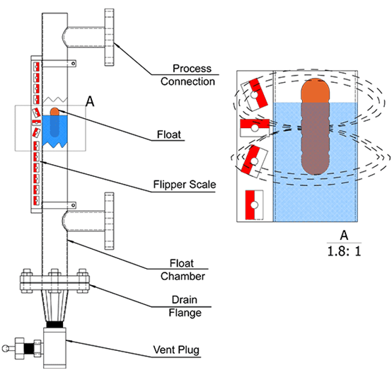
2. Float level gauge
Principle: The structure of the float level gauge is designed and produced mainly based on the principles of buoyancy and static magnetic field. The position of the float with a magnet (referred to as the float) in the measured medium is affected by the buoyancy: the change in liquid level causes the change in the position of the magnetic float. The magnet and sensor (reed switch) in the float change the number of components (such as fixed resistors) connected in series in the circuit, thereby changing the electrical quantity of the instrument circuit system. That is, the change in the position of the magnetic float causes the change in the electrical quantity. The liquid level in the container is reflected by detecting the change in the electrical quantity.
3. Steel belt level gauge
Principle: It is designed and manufactured based on the principle of mechanical balance. When the liquid level changes, the original mechanical balance will reach a new balance through the movement of the steel belt under the disturbance of the float by the buoyancy. The liquid level detection device (float) drives the steel belt to move according to the liquid level. The displacement transmission system drives the transmission pin to rotate through the movement of the steel belt, and then acts on the counter to display the liquid level.
4. Radar level meter

Principle: Radar level meter is a measuring instrument based on the time travel principle. Radar waves run at the speed of light, and the running time can be converted into a level signal through electronic components. The probe emits a high-frequency pulse and propagates along the cable probe. When the pulse encounters the surface of the material, it is reflected back and received by the receiver in the instrument, and the distance signal is converted into a level signal.
5. Magnetostrictive level gauge
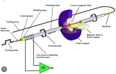
Principle: When the sensor of the magnetostrictive level gauge is working, the circuit part of the sensor will stimulate a pulse current on the waveguide wire, and when the current propagates along the waveguide wire, a pulse current magnetic field will be generated around the waveguide wire. A float is provided outside the sensor rod of the magneto strictive level gauge, and the float can move up and down along the rod as the liquid level changes. There is a set of permanent magnetic rings inside the float. When the pulse current magnetic field meets the magnetic ring magnetic field generated by the float, the magnetic field around the float changes, so that the waveguide wire made of magnetostrictive material generates a torsional wave pulse at the position of the float. This pulse is transmitted back along the waveguide wire at a fixed speed and detected by the detection mechanism. By measuring the time difference between the pulse current and the torsional wave, the position of the float, that is, the position of the liquid level, can be accurately determined.
6. Radio frequency admittance level meter
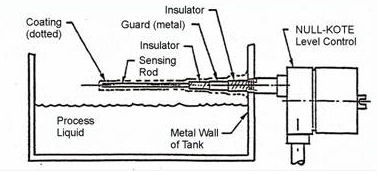
Principle: The radio frequency admittance level meter consists of a sensor and a control instrument. The sensor can be installed on the top of the silo using a rod, coaxial or cable probe. The pulse card in the sensor can convert the level change into a pulse signal and send it to the control instrument. The control instrument converts it into an engineering quantity after calculation and processing , thereby realizing continuous measurement of the level.
7. Tuning fork level meter
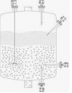
Principle: The working principle of the tuning fork level controller is to make the tuning fork vibrate at a certain resonant frequency through a pair of piezoelectric crystals installed on the tuning fork base. When the tuning fork comes into contact with the measured medium, the frequency and amplitude of the tuning fork will change. These changes are detected, processed and converted into a switch signal by the intelligent circuit.
8. Glass plate level gauge (glass tube level gauge)
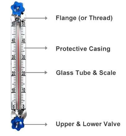
Principle: The glass plate level gauge is connected to the container through a flange to form a communicating vessel. The height of the liquid level in the container can be directly read through the glass plate.
![]()
Principle: The pressure level gauge adopts the static pressure measurement principle. When the liquid level transmitter is put into a certain depth in the measured liquid, the sensor faces the pressure on the liquid surface, and at the same time, the liquid pressure is introduced into the positive pressure cavity of the sensor through the gas-conducting stainless steel. Then, the atmospheric pressure Po on the liquid surface is connected to the negative pressure cavity of the sensor to offset the Po on the back of the sensor, so that the pressure measured by the sensor is: ρ. gH . By measuring the pressure P, the liquid level depth can be obtained.
10. Capacitive level meter
Principle: Capacitive level gauge measures the height of liquid level by measuring the change of capacitance. It is a metal rod inserted into a liquid container, with the metal rod as one pole of the capacitor and the container wall as the other pole of the capacitor. The medium between the two electrodes is the liquid and the gas above it. Since the dielectric constant ε1 of the liquid is different from the dielectric constant ε2 on the liquid surface, for example: ε1>ε2, when the liquid level rises, the total dielectric constant value between the two electrodes of the capacitive level gauge increases accordingly, and thus the capacitance increases. Conversely, when the liquid level drops, the ε value decreases, and the capacitance also decreases. Therefore, the capacitive level gauge can measure the height of the liquid level by the change of the capacitance between the two electrodes.
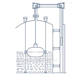
![]()
Principle: The float is immersed in the liquid in the float chamber and is rigidly connected to the torque tube system. The force borne by the torque tube system is the net value of the float's own weight minus the buoyancy of the float. Under this combined force, the torque tube twists a certain angle. Changes in the position, density or interface height of the liquid in the float chamber cause changes in the buoyancy of the float immersed in the liquid, thereby changing the rotation angle of the torque tube. This change is transmitted to the sensor rigidly connected to the torque tube, causing the sensor output voltage to change, which is then amplified by the electronic components and converted into a 4-20mA current output. The float level transmitter uses a microcontroller and related electronic circuits to measure process variables, provide current output, drive LCD display and provide HART communication capabilities.
12.Electric contact level gauge
Principle: The electric contact water level gauge is designed based on the different resistivity of water and steam. The impedance of the measuring tube's electrodes to the tube is small in water. The impedance to the tube is large in steam. As the water level changes, the number of electrodes in the water changes. This is converted into a change in resistance value. This is transmitted to the secondary instrument, thereby realizing functions such as water level display, alarm, and protection interlocking .
13.Magnetic two-color electronic level meter
Principle: The magnetic sensitive electronic two-color liquid level gauge is made of high-quality stainless steel and imported electronic components. The display part adopts high-brightness LED two-color light-emitting tube to form a columnar display screen. The upper and lower limit alarm and control of the liquid level can be realized through the red and green changes of the LED light column.
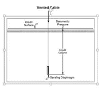
Principle: The static pressure level transmitter encapsulates the diffused silicon oil-filled core in a stainless steel housing. The front protective cap protects the sensor diaphragm and allows the liquid to contact the diaphragm smoothly. The waterproof wire is sealed and connected to the housing. The ventilation pipe is connected to the outside world in the cable, and the internal structure is designed to prevent condensation .
15.Ultrasonic level meter
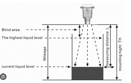
Principle: Ultrasonic level meter / level meter is composed of a complete ultrasonic sensor and control circuit. The ultrasonic wave emitted by the ultrasonic sensor is reflected by the liquid surface, and the time required for return is used for calculation. The temperature effect during the ultrasonic transmission process is corrected by the temperature sensor and converted into the distance between the liquid surface and the ultrasonic sensor. It is displayed on the LCD and outputs a 4mA-20mADC analog signal to realize remote reading of field instruments.
16.Differential pressure level gauge (double flange level gauge)
Principle: The differential pressure level transmitter measures the difference between high and low pressures, and then converts it into a current signal by the conversion component and transmits it to the electrical components in the control room. The differential pressure level gauge is mainly used for level measurement of sealed pressurized containers. The size of the differential pressure also represents the size of the liquid level. The differential pressure gauge is used to measure the differential pressure between the gas and liquid phases to know the liquid level.

 +86 21 59241315
  sales@xvyanprecision.com
 No 969, YunHan Road Pudong District Shanghai City China
  +86 21 59241315
  sales@xvyanprecision.com
 No 969, YunHan Road Pudong District Shanghai City China
  +86 21 59241315
  sales@xvyanprecision.com
  Global
 English
 中文
中文 日本語
日本語 한국어
한국어 français
 Deutsch
 Español
 русский
 português
 العربية
 tiếng việt